Learning about Logic Gates
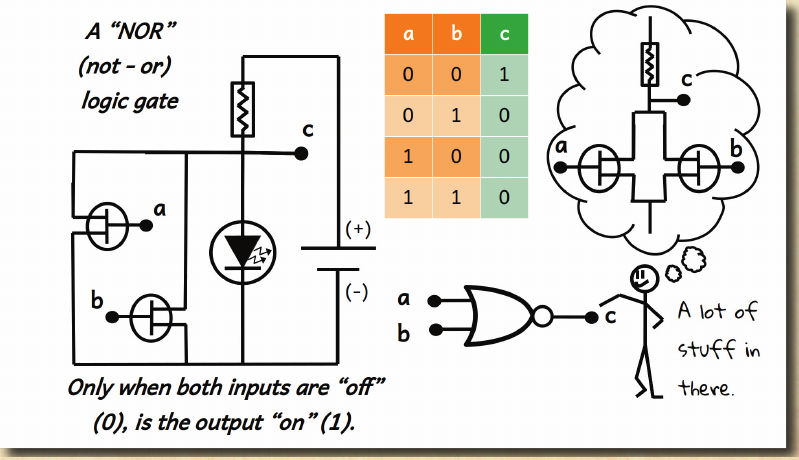
NOR Gate Example from The Wonderful Wizard of Electronics

Input X
0
Output X̄
1
| X | X̄ |
|---|---|
| 0 | 1 |
| 1 | 0 |
Click & hold the input dot to send a 1 into the gate.
And Here is the SR Flip-Flop from The Wonderful Wizard of Electronics Appendix

S
0
R
0
Q
0
Q̄
1
| S | R | Q | Q̄ | |
|---|---|---|---|---|
| 0 | 0 | Q | Q̄ | Hold |
| 1 | 0 | 1 | 0 | Set |
| 0 | 1 | 0 | 1 | Reset |
| 1 | 1 | ✗ | ✗ | Invalid |
Click & hold S (bottom-left) to Set, or R (top-left) to Reset. Release to see the latch hold state.
Always Keep Learning
Try Logic.ly's online simulator.
Build and test simplified logic circuits. This video shows a binary counter using T-Flip Flops. Click here to go to their site.Free Circuit Simulators
If you want a full-fledged SPICE circuit simulator for your circuits class, consider the open-source Quite Universal Circuit Simulator (QUCS), or LTSpice or even ngspice.There is obviously a long progression of learning, and while some of these tools are "professional grade" number crunchers, they can still support a younger student simulating the most basic functions. Learning a free toolset that can carry a student through literally decades of learning and career is one of the actually-good things that the internet has made possible!